References
LAKASA Oil Interceptor
LAKASA Oil Interceptor is required wherever lubricating oil, cutting oil, kerosene, gasoline, naptha, paraffin, trisod phosphate and numerous other light density and volatile liquids are present in the drainage. In commercial establishments such as service stations, garages, auto-repair shops, dry cleaners, laundries industrial plants or process industries having machine shops, metal treating process rooms, chemical process or mixing rooms, etc, there is always the problem of flammable or volatile liquids entering the drainage system which can contaminate the sewer line and cause a serious fire or explosive condition. The discharge of oily wastewater, which consists of high degree of BOD (Biological Oxygen Demand), COD (Chemical Oxygen Demand), FOG (Fat, oil and grease), and other organic wastes into natural waterways has disastrous impacts on aquatic life and the environments.
LAKASA Oil Interceptor is a preliminary treatment for oily (hydrocarbon) wastewater discharged from sources such as service & repair workshop, carwash bays etc. The effluent from the interceptor should be channeled to sewer line for further process and treatment. LAKASA Oil Interceptor is designed to allow introduction of any liquid types for separation as long as there is sufficient specific gravity differential to permit gravitational separation. When the liquid temperature is about 20oC, the Water Specific Gravity is 0.998; whereas, the Oil Specific Gravity is 0.92
It is also take into account that the water flow is intermittent and variable and the oil or any combination is non-emulsified oil/water mixtures. The design also allows the intercepted oil to be automatically drawn-off for storage in a continuous operation. Sediment should be removed from sediment bucket at regular intervals. To eliminate pressure build-up inside the interceptor, a vent connection on side of the body allows the venting of interceptor.
Oil in Water Coalescing Media – How It Works
LAKASA Oil Interceptor contains a coalescing medium or media. This media provides a suitable surface for oil droplets to meet and grow, or coalesce, into larger droplets. As oil droplets grow in size the buoyancy of the droplets increases. The droplets rise towards the surface of the water due to the fact that the specific gravity of oil is less than the specific gravity of water. In this way the oil will form a layer that can be skimmed manually or to be channeled into a separate storage tank, pending for proper disposal.
As oil droplets coalesce into larger droplets, the buoyancy of the droplets increases. This reflected in the known rise time for a given size of oil droplet. The more efficient the coalescence action of the media, the larger the oil droplets become. Larger oil droplets result in reduced rise time. Shorter rise time will certainly increase and improve the efficiency and effectiveness of Oil Interceptor.
Coalescing plates offer high efficiency and low operating and maintenance costs because there are no moving parts and no replacement parts are needed or spent absorbents generated.
| Time needed for oil droplet (0.85Sp.Gr.)
in water to rise 3 inches |
|
| Droplet size, microns | Rise Time |
| 300 | 12 seconds |
| 150 | 42 seconds |
| 60 | 4 min 12 seconds |
Notes to follow to generate good effluent
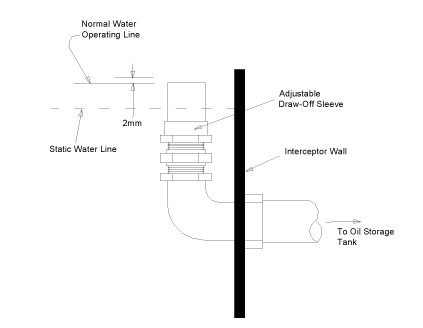
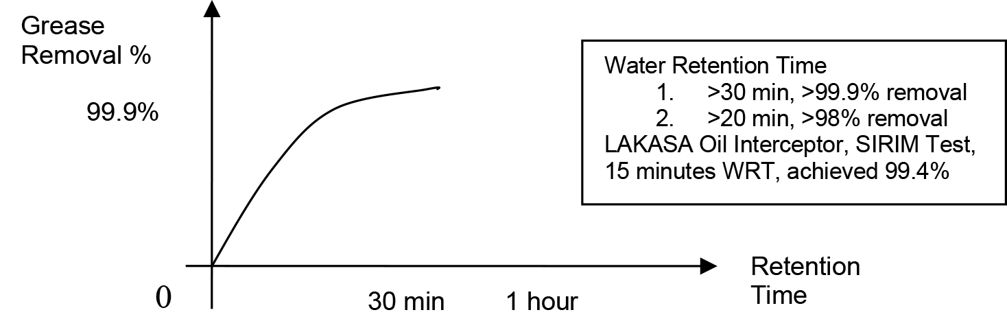
- Sizing of interceptor meets the requirement. Water flow rates are within the specification. Adequate water retention time will ensure proper separation of oil/ water mixture.
- Perforated bucket at sludge chamber should be inspected and cleaned on a regular basis. Sludge and deposits present in the oil will significantly reduce the effectiveness of the interceptor.
- Hydrocarbons entering the separator will be in a free non-emulsified state and capable of being separated from water by gravity separation.
- Detergent will emulsified the oil and allow it to enter the sanitary sewer system because detergents have a definite affinity for hydrocarbons. Wash water from truck washing racks must be routed directly to a sanitary sewer or treated with special equipment.

ONE YEAR WARRANTY ON WELDING JOINTS (LEAKAGE) FOR LAKASA OIL INTERCEPTOR
Dimensional Data (All dimension in mm)
| Model | Flowrate (GPM) | Flowrate (litre / second) | Inlet & outlet pipe | A (length) | B (width) | C (height) | E | F | G | H | Weight*(full)(»kg) |
| LK3015A | 15 | 1.14 | 50 | 600 | 450 | 430 | 110 | 320 | 200 | 150 | 120 |
| LK3020A | 20 | 1.50 | 75 | 780 | 470 | 450 | 110 | 340 | 220 | 200 | 150 |
| LK3025A | 25 | 1.89 | 75 | 800 | 500 | 480 | 110 | 370 | 250 | 250 | 200 |
| LK3035A | 35 | 2.65 | 100 | 880 | 550 | 500 | 110 | 390 | 270 | 300 | 240 |
| LK3050A | 50 | 3.78 | 100 | 930 | 600 | 550 | 130 | 420 | 300 | 350 | 300 |
| LK3075A | 75 | 5.68 | 100 | 1220 | 800 | 620 | 130 | 490 | 370 | 400 | 550 |
| LK3100A | 100 | 7.57 | 100 | 1450 | 900 | 750 | 180 | 570 | 450 | 450 | 1000 |
| LK3150A | 150 | 11.35 | 100 | 1650 | 1000 | 850 | 180 | 670 | 550 | 500 | 1500 |
| LK3200A | 200 | 15.14 | 150 | 1850 | 1100 | 1000 | 210 | 790 | 670 | 550 | 1800 |
| LK3250A | 250 | 18.92 | 150 | 2050 | 1220 | 1140 | 210 | 930 | 810 | 600 | 2700 |
| LK3300A | 300 | 22.70 | 150 | 2440 | 1220 | 1220 | 210 | 1010 | 890 | 650 | 3000 |
| LK3350A | 350 | 26.49 | 150 | 2440 | 1220 | 1460 | 210 | 1250 | 1130 | 700 | 3300 |
| LK3400A | 400 | 30.28 | 150 | 2750 | 1220 | 1500 | 210 | 1290 | 1170 | 750 | 3800 |
| LK3500A | 500 | 37.84 | 150 | 2770 | 1500 | 1500 | 210 | 1290 | 1170 | 800 | 4500 |
| LK3600A | 600 | 45.41 | 150 | 3000 | 1500 | 1850 | 250 | 1600 | 1480 | 850 | 6000 |
| LK3700A | 700 | 52.98 | 200 | 3000 | 1500 | 2200 | 250 | 1950 | 1830 | 900 | 8500 |
* Full weight means when full with water & solid waste
Environmental Quality Act, 1974 (will not applicable to the following)
- Processing, manufacturing, washing or servicing of any other products or goods :
- That produce effluent of less than 60 cubic metres (13,000 imperial gallons) per day ;
- That the effluent of which does not contain those contaminants listed as parameters (6) to (16) in the first column of the Third Schedule ;
- Where the total load of biochemical oxygen demand of the effluent fixed at 20 degree centigrade for 5 days or suspended solid or both, shall not exceed 6 kilogrammes per day (concentration 100 miligrammes per litre) ;
- In any housing or commercial development or both of less than 30 units, without affecting the generality of the (3) above.
For application whereby it need to meet the requirement of the Environment Quality Act, 1974, Standard B on the oil & grease of 10mg/l of effluent quality, LAKASA Oil Interceptor should be sized with the Water Retention Time (WRT) of more than 30 minutes. This will normally be able to produce the effluent result with >99.9% grease & oil removal and to achieve the Standard B and to produce an average effluent of 10mg/l.
Operation and Maintenance Guide
The oil shall be skimmed and dirt, sand and sludge shall be removed on a quarterly basis at a minimum. Oil shall be handled as a hazardous waste stored and sent to a used oil recycler. If the oil is too thin to pump or skim, oil absorbent pads or pillows can be used to remove the oil. These can be sent for disposal or recycling, or if oil can be removed from them they can be reused (oil collected and sent for recycling).
The first quarter’s sludge/dirt shall be sent for waste characterization to determine if it can be disposed off as ordinary waste or hazardous waste. If hazardous, sludge shall be stored in labeled drums and picked up by a licensed hauler. If non-hazardous, sludge shall be disposed off to a landfill, and is not to be deposited on-site.
- Manual draw off of oil.A routine inspection of oil interceptors should be undertaken at least once every 3 months by the inspection technician. Using a dipstick, the amount of accumulated oil and solids shall be measured to determine if a clean-out is required. Servicing and clean-out of oil to a separate storage tank pending for proper disposal whenever is necessary.
- Automatic draw off of oil.During the first 2 weeks of operation, check the oil storage tank for oil build up to determine the frequency it needs to be emptied. If water is found entering the draw-off sleeve into the oil storage tank during normal working condition, adjust the draw off level upwards from 2 mm to 5 mm.
Installation method statement
- Inspect unit for defects / damages and make sure it meets specified requirements (eg : model and size).
- DO NOT INSTALL INTERCEPTOR BACKWARDS. Install interceptor as close as possible to the source to minimizes unprotected pipe.
- Install interceptor sitting on floor, partially recessed or flush-to-floor, making sure there is enough room to allow for easy maintenance of the unit. (Room for cover to be removed and sediment bucket to be taken out for cleaning).
- INTERCEPTOR MUST BE PLACED ON A FLAT, SOLID SURFACE TO SUPPORT THE BOTTOM! When suspending interceptor from floor above, all units must be fully supported on bottom with a flat surface strong enough to support the weight of the unit when full of water/sediment waste. All units must be independently supported to avoid stress on fittings.
- WHEN INSTALLING IN THE GROUND, Construct a solid manhole sump for housing the interceptor. Manhole sump cover should normally be higher a bit the floor level OR construct a drain surrounding the cover to channel away most rain water and prevent in from entering the sump. The sump should also allocate four corner Water Exit at lowest possible 4 sides corners for the in case splashed into rain water to escape and seep into the earth outside the sump.
- Connect a ventilation pipe to the interceptor. This is to eliminate pressure build-up inside the interceptor.
- For automatic oil draw off by gravity flow, connect the interceptor to an oil storage tank for receiving and storing oil pending for proper disposal. For manual draw off of oil, seal up the connection
- FILL INTERCEPTOR WITH WATER AND INSTALL LID BEFORE BACK FILLING. It is recommended to use light sand for back fill. Be sure backfill is free of sharp stones and foreign matter to avoid punctures. (DO NOT PUT SAND INTO INTEREPTOR!)
- INTERCEPTOR filled with clean water until static water level and is ready for operation.
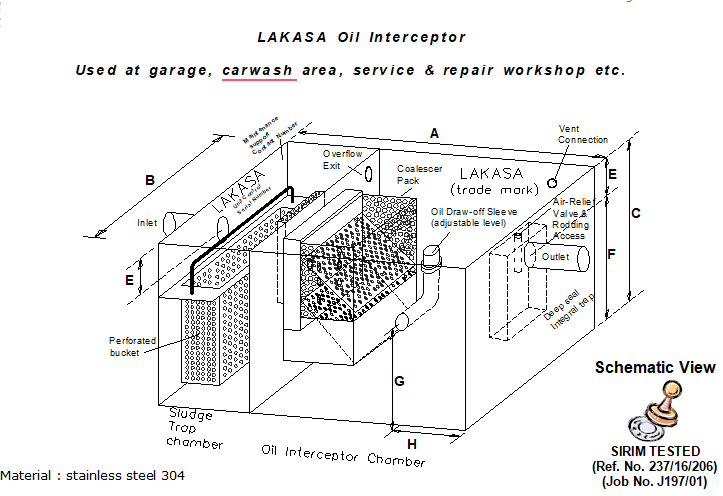
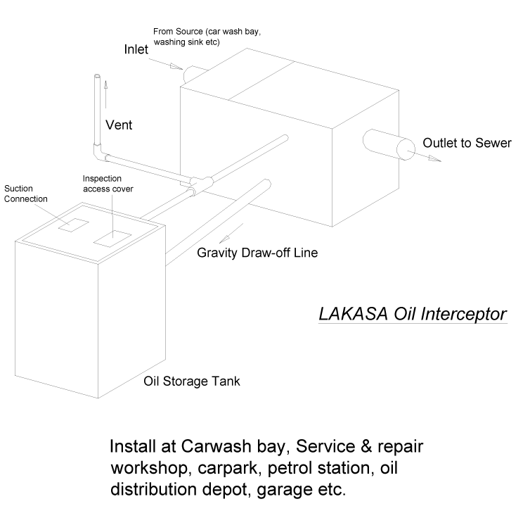
Sizing of LAKASA Oil Interceptor
In order to work effectively, the amount of wastewater flowing into the interceptor needs to be calculated. An estimate of the peak water flow during the washing process, the pattern of water flow (continuous flow throughout the day or just intermittent water flow, on and off for every interval period). The Volume as well the Pattern of water flow is the key contributor to the high or low Water Retention Time (WRT) achieved.

1) Calculation by number of fixtures
Peak flow rate
Total nos. of hose outlet that continuous discharging to drain line at a particular time
Example
A carwash area, equipped with 2 water hoses, used for car washing.
Each hose generates a water flow rate of about 8 GPM (example). Thus the estimated peak water flow is 8 GPM x 2 = 16 GPM .
Scenario 1 (Very busy working environment)
If continuous water flow thru-out the day.
- To achieve Retention Time of 30 minutes : 16GPM x 30 min = 480 gallons.
- To propose model LK3250A (250 GPM), which has a volume capacity of approx.. 500 gallons
Scenario 2 (Not busy working environment)
If Waterflow continuously for 5 minutes at every interval of 30 minutes.
- To achieve Retention Time of 30 minutes : 16GPM x 5 = 80 Gallons
- To propose model LK3075A (75 GPM), which has a volume capacity of approx.. 103 gallons
2) Calculation by area (open area, subject to rainfall, example : Car Park)
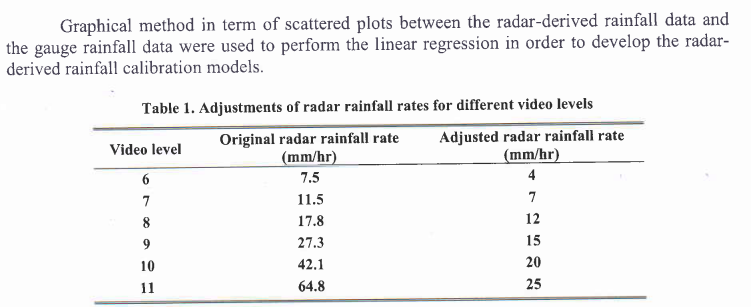
Rainfall estimation in Peninsular Malaysia : Article Extract

| Rainfall | Total area (length x width in meter) x rainfall |
| Waterflow | Length 30m, width 15m, rainfall : 25mm / hour
(assumed average figure)
Rainfall water flow = 30 x 15 x 25 ÷ 3600 = 3.125 liter/sec |
- To achieve WRT of 30 minutes : 3.125 x 30 X 60 = 5625 litres = 1240 gallons
- To propose model LK3500A (500 GPM), which has a volume capacity of 1240 gallons.
Sizing of Oil Storage Tank
- Estimate the volume of oil into the interceptor
- Frequency of maintenance routine (once a month, twice a month, etc)
- Calculate the tank size required to cater for the total accumulated oil during the period
Oil Storage Tank Dimensional Data
| Model | Tank Capacity (litres) | Length (mm) | Width (mm) | Height (mm) | Recommended for |
| LS015 | 110 | 600 | 450 | 430 | 15 GPM |
| LS020 | 160 | 780 | 470 | 450 | 20 GPM |
| LS025 | 190 | 800 | 500 | 480 | 25 GPM |
| LS035 | 240 | 880 | 550 | 500 | 35 GPM |
| LS050 | 300 | 930 | 600 | 550 | 50 GPM |
| LS075 | 600 | 1220 | 800 | 620 | 75 GPM |
| LS100 | 800 | 1220 | 900 | 750 | 100 GPM |
| LS150 | 900 | 1220 | 900 | 850 | 150 GPM |
| LS200 | 1000 | 1220 | 900 | 1000 | 200 GPM |
| LS250 | 1200 | 1220 | 900 | 1140 | 250 GPM |
| LS300 | 1300 | 1220 | 900 | 1220 | 300 GPM |
| LS350 | 1700 | 1220 | 950 | 1460 | 350 GPM |
| LS400 | 2000 | 1220 | 1130 | 1500 | 400 GPM |
| LS500 | 2500 | 1380 | 1220 | 1500 | 500 GPM |
| LS600 | 2700 | 1220 | 1220 | 1850 | 600 GPM |
| LS700 | 3200 | 1220 | 1220 | 2200 | 700 GPM |
Material : stainless steel 304